Alternators
The simplest way to generate alternating current is to rotate a conductor loop in a homogeneous and temporally constant magnetic field. The Lorentz force acts on the part of the conductor loop that is perpendicular to the magnetic field lines, which generates an induction voltage at the open ends of the conductor loop.
Since the magnetic field lines in this example run vertically, the induction voltage is always greatest when the conductor loop is in a horizontal position. If, on the other hand, it is vertical and thus parallel to the field lines, the induction voltage disappears. At all points in time between these extremes, the voltage has a defined but time-changing course. The exact course can be calculated mathematically using Faraday's law of induction as follows: The projection of the surface that is perpendicular to the field lines can be described analogously to an oscillation by a sine function with the angular frequency $\omega$, i.e. the following equation has to be applied:
$$A = A_0\sin\omega t$$
This would mean that the conductor loop would be aligned parallel to the field lines at time $t=0$. With
$$U_\mathrm{ind} = B\frac{\mathrm{d} A}{\mathrm{d} t}$$
then applies to the induction voltage
$$\boxed{U_\mathrm{ind} = BA_0\omega\cos\omega t}$$
As expected, the course of the induction voltage over time can then be described with the cosine function. This equation says that the change in $A$ has its largest value at $t=0$, although the area has its minimum at this given point in time. The greatest possible voltage that is present at the amplitudes is called
peak voltage. If you connect a load to the ends of the conductor loop, for example, an ohmic resistor, then a current flows whose time profile is identical to that of the induction voltage. Since the polarity reverses again and again over time, unlike DC voltage, there is no longer a fixed polarity. Depending on the angular frequency, this reverses again and again, which also periodically changes the flow direction of the electrons.
In practice, when generating electricity in power plants, not just one but three coils are used, which are offset from each other by $120^\circ$ on a circle. This is done with the help of a rotating permanent magnet that induces an alternating voltage in each of the three coils. However, the magnetic field in power plants is not generated by a permanent magnet, but instead by a current-carrying coil (electromagnet). One connection each of the three coils is connected to each other and forms the so-called
neutral conductor. The other connection of a coil is called the phase. These three phases $P_1$, $P_2$ and $P_3$ are transported separately into the building via different lines. The current generated in this way is therefore called
three-phase alternating or briefly
three-phase current. The neutral conductor is additionally grounded
protective grounding. If an apparatus has a connection to the ground, there is additional protection against electric shock, because the current is then diverted from the phase via earth. The main frequency in Europe has a frequency of 50 Hz and the voltage of each phase is 230 V compared to the neutral conductor. If, on the other hand, two phases are switched against each other, the voltage is greater by the factor $\sqrt{3}$ due to the phase shift of $120^\circ$.
This page contains 661 words and 4028 characters.
Last modified: 2022-10-01 18:38:25 by mustafa
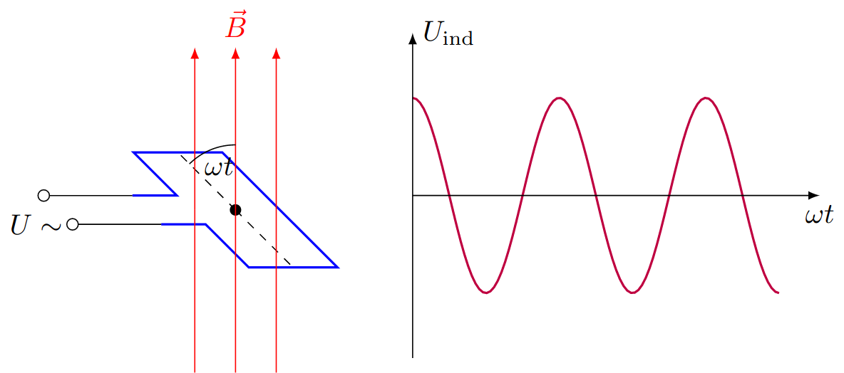 Simple generator of electrical energy with a rotating wire inside a magnetic field.
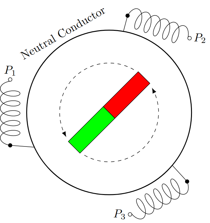 Sketch of a three-phase current generator consisting of a rotating magnet and three coils.

