Hall Effect
The hall effect is related to the Lorentz force acting on electrons inside a wire. It was named after the American physicist Edwin Hall and is used to measure the strength of magnetic fields. The strength of magnetic fields is usually measured with calibrated Hall probes, whereby the measuring principle is based on the Hall effect. The following figure illustrates this principle with the help of a conductor placed inside a magnetic field with the strength $B$. The magnetic field lines are parallel to the side $b$.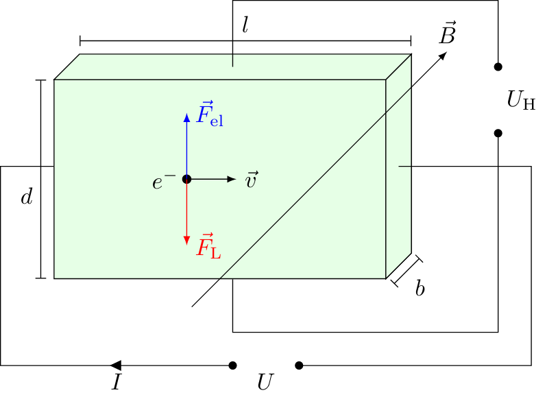 Sketch for deriving the Hall effect.
 Hall Voltage
The Hall voltage increases with a larger current and magnetic flux density but it is inversely proportional to the electron density and the thickness of the conductor in the direction of the magnetic field lines. For this reason, semiconductors with fewer free electrons are usually more suitable than highly conductive metals. And in addition, the sensitive material has to be very thin, in order to decrease the value of $b$. Nevertheless, the achievable Hall voltages are usually so small that they have to be additionally amplified with voltage amplifiers in order to deliver an adequate signal.
Some textbooks do not directly give an overview of the electron density $n$ but instead define a material-dependent Hall constant as follows.
If an electric current $I$ flows through a conductor which is placed into a magnetic field, and has the width $b$ in field direction, then a hall voltage is induced which can be calculated according to $$U_\mathrm{H} = \frac{IB}{neb}$$ It additionally depends on the electron density $n$ of the conducting material.
Hall constant
In this case, the formula for Hall voltage can be written down as follows:
$$\boxed{U_\mathrm{H} = A_\mathrm{H}\frac{IB}{d}}$$
The sign of the Hall constant depends on whether the current is predominantly caused by electrons, as in metal, or by holes, as in semiconductors. The Hall constants are usually difficult to determine and scatter very widely. Tiny impurities and temperature fluctuations have a very large impact on the measured value. The hall constant of a material is defined as the inverse electron density $n$ multiplied with the elementary charge $e$: $$A_\mathrm{H} = \frac{1}{ne}$$
This page contains 657 words and 3921 characters.


Last modified: 2022-10-01 18:38:08 by mustafa